
+86 188-1951-9629
There are many plastic processing methods in daily life, and the extrusion slot-die coating process is one of the common techniques used to produce practical semi-finished products from raw plastic materials.
Innovation in this field stems from competition with other manufacturing processes, new product concepts, and economic pressures—posing continuous challenges for extrusion equipment manufacturers to improve their technologies. Extrusion systems are classified based on the die exit geometry, resulting in four main categories: circular, slot (flat), annular, and free-form two-dimensional.
In all these types, plastic shaping occurs while the material is in a molten state. From a fluid dynamics perspective, this molten condition is governed by numerous rheological phenomena. Many of these phenomena are not yet fully understood, and only a few key characteristics have been modeled satisfactorily. Industry techniques for characterizing flow behavior range from simple measurements like Melt Flow Index (MFI) to advanced methods that define relationships between viscosity and elasticity, and even real-time online measurements using ultrasonic technology. Recent theoretical and experimental research—aimed at describing flow performance within extrusion dies—has significantly improved understanding of the processes occurring inside the die by leveraging material data and flow modeling.
For pipe extrusion, center-fed dies are commonly used for most plastic profiles. In contrast, dies for blown film, reinforced pipes, plastic bubbles, and wire/cable coating are typically fed from the side at a 90-degree angle. When designing an extrusion slot-die coating head, combinations of different die types and feed directions are often employed.
Regardless of configuration, the die must be integrated with the die base—either directly or via a replaceable adapter—through a hot runner system that reassembles the melt stream. The design of these flow channels is closely tied to the specific product and material, exhibiting relatively low standardization. For example, when producing PVC pipes with a spider mandrel die, compression toward a smaller exit cross-section is critical for ensuring product quality. In most cases, pipe and bubble extrusion involve a reduction in diameter, with typical draw-down ratios ranging from 2:1 to 6.5:1. Conversely, blown film dies and large-diameter pipe dies often feature an expansion at the die exit, with cross-sectional area increases up to a ratio of 1:2.5. In all cases, the flow channel should provide continuous acceleration, particularly in the die lip (nozzle) region.
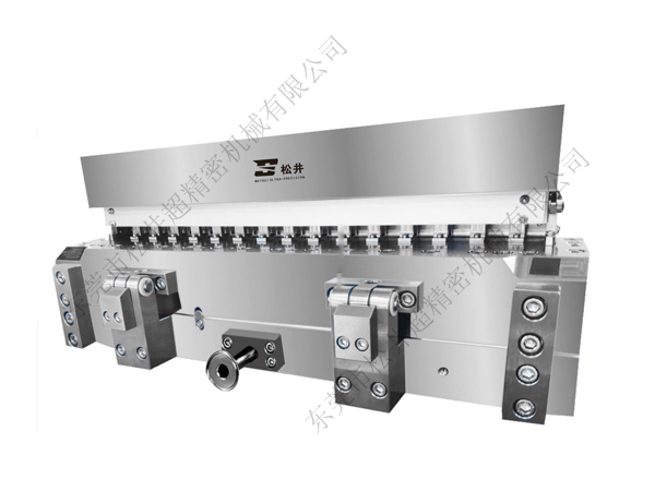
In many designs, the land length (parallel zone) at the end of the die lip can be adjusted according to the slot width. The so-called "flexible ring" (or "curved ring") technology enables more precise adjustment of the die gap and compensates for thickness variations—a technique that has gained recognition in pipe and blown film applications only in recent years. This technology involves replacing a rigid outer die ring near the feed zone with an elastic sleeve. Evenly spaced adjustment screws are mounted on the outer ring, allowing controlled, reversible deformation of the elastic sleeve to precisely regulate local flow resistance through the annular die gap. The ratio of die land length to die gap width depends on the processed material; for pipe dies, this ratio typically ranges from 2:1 to 30:1.