+86 188-1951-9629
Slot-die coating is an advanced pre-metered coating technology capable of achieving high-precision coatings. Currently, the lithium-ion power battery industry has widely adopted slot-die extrusion coating technology to manufacture battery electrodes.

As illustrated in Figure 1, a slurry with a controlled flow rate enters the die cavity through the inlet of the slot-die head, builds up stable pressure inside, and is finally extruded uniformly through the narrow slit at the die exit onto the foil substrate.
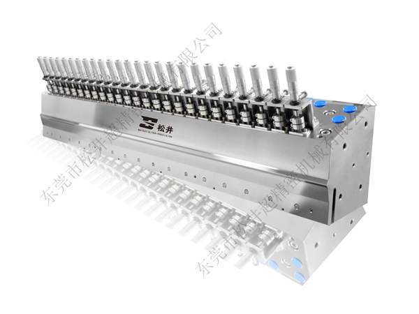
The slot-die is a critical component in lithium battery coating processes, directly determining the quality and uniformity of the coated electrode. Consequently, the cost of the die typically accounts for more than 30% of the entire coating head assembly. The die structure primarily consists of three parts: the upper die, the lower die, and shims. The lower die features a specially designed internal cavity, while the upper die is relatively simpler in structure. Shims, positioned between the upper and lower dies, can be selected according to different coating configurations, as shown in Figure 2. Key factors affecting coating thickness uniformity include the uniformity of the exit velocity from the die cavity, substrate flatness, slurry homogeneity, and surface tension—among which the uniformity of the die exit velocity is one of the most critical. The geometric design of the die cavity directly influences the flow field pattern within; optimizing structural parameters can effectively enhance the uniformity of the exit velocity distribution. Today, numerous domestic companies have independently developed and designed coating dies, with design optimizations including:
(1) Internal flow channel design of the coating die, such as tapered, coat-hanger, single-cavity, and dual-cavity manifold structures. The goal is to maintain consistent slurry flow velocity within the die, avoiding stagnant zones or particle settling, thereby ensuring uniform exit velocity at the die slit and consistent coating thickness. (A detailed summary will be provided in a future article.)
(2) Optimization of inlet location—for example, bottom-fed or side-fed die configurations—to modify fluid flow dynamics and ensure uniform exit velocity across the die slit.
(3) Optimized shim structure design.